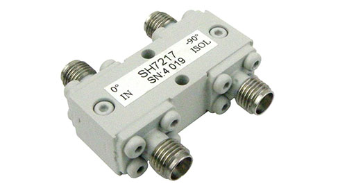
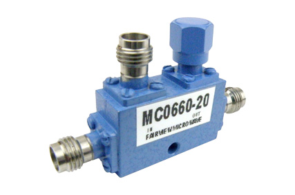
A 90 Degree Hybrid Coupler is a one of the few hybrid coupler types, the others include 180 degree hybrid couplers and 0 degree hybrid couplers. 90-degree hybrid couplers are also known as quadrature couplers/hybrids, as any signal injected into any port will result in two 90 degree out-of-phase signals present on the other two ports. The output signals in a 90-degree hybrid coupler are typically split evenly between the two output ports, meaning that the signal energy is 3dB (half signal strength) less at the outputs than the inputs, but otherwise identical except for being out-of-phase by 90 degrees.

90 Degree Hybrid RF Coupler
Related articles
Peter McNeil | Aug 10, 2022 | RF Couplers
A RF Coaxial Hybrid Coupler is a type of RF coupler that essentially behaves as an equal power splitter while also creating a phase shift between the two ports. RF hybrid couplers are generally distinguished by the degree of the phase shift, be it 0 (no phase shift and just a 4-port directional coupler), 90, or 180. A unique attribute about RF hybrid couplers is that the phase shift between the coupled ports is broadband. Other important metrics of a hybrid coupler are the phase balance, amplitude balance, and the extent of the isolation between the coupled (output) ports.

RF Hybrid Coaxial Coupler
As such, RF hybrid couplers are a special case of four-port directional couplers, which is specifically designed to have a 3dB coupling, or equal power split, and 90- or 180-degree phase shift between the coupled ports. Like with a four-port directional coupler it is critical for the design of an RF hybrid coupler to be as symmetric as possible. The accuracy of a hybrid coupler phase shift is only good to a certain bandwidth. This is also true for the amplitude balance, phase balance, and isolation. Hence, a hybrid coupler is generally only specified over a broad, but fixed, bandwidth based on what is considered a reasonable threshold for these metrics.
180-degree Hybrid couplers are sometimes realized using a rat race coupler designed in a specific way to realize the desired coupling and phase shift between the ports. It is important in the design of a hybrid coupler to achieve low VSWR, isolation, and phase/amplitude balance, which is often why a rat race coupler design is chosen. Another method is to modify a branchline coupler designed as a 90-degree hybrid and adding a 90-degree section to one of the branchline coupler ports.
A use case of hybrid couplers is to enhance the isolation between two RF signal paths that cross each other. Other methods of achieving this could be to use an airbridge or a wire bond cross over to provide physical isolation. A planar hybrid coupler, on the other hand, can be used to isolate two crossed paths in-plane. All that is required is to cascade two hybrid couplers together, and the four-port network that results has isolation between the two RF paths. It should be noted that this method does limit the bandwidth of the signal paths and does require significant board or die real estate.
Learn more about 90 Degree Hybrid Couplers in this post by Fairview Microwave: /content/fm/en/blog/archives/2022/what-is-a-90-degree-hybrid-coupler.html

Peter McNeil | Feb 06, 2025 | RF Couplers
There are many instances in military/defense, aerospace, space, and naval applications where there is a need for sampling signals from high power transmission paths or monitoring the frequency of high-power signal paths. In these cases, the best RF component for the job is often an RF coupler. However, not all RF couplers are designed for extreme environmental applications indicative of the requirements for defense applications.
For instance, many RF couplers have coaxial connector ports either for the primary signal paths or the coupled ports. If the coaxial connector ports are coaxial types that use dielectric spacers, it may be that the dielectric material used can’t sufficiently perform under extreme temperature ranges specified for military grade coaxial connectors. Other environmental features include corrosion resistance, shock, vibration, humidity, altitude/pressure, etc.
Generally, standard waveguide flanges can meet all of these requirements, possibly with the exception of corrosion resistance. This is why many waveguides meant for defense applications are gold plated; this helps prevent corrosion while still maintaining high conductivity for low loss performance. A common standard for body plating specifications for waveguide couplers is MIL-DTL-5541.
Even with waveguide couplers, if the attachment methods of the coupled ports aren’t designed to withstand shock and vibration, the joint between the main waveguide and coupled waveguide may degrade or even fail. Hence, it is often imperative to ensure that even waveguide couplers are designed to meet MIL-Spec standards for ruggedness. For altitude/pressure performance, couplers often need to be sealed, either hermetically or with epoxy, to prevent outgassing or debris ingress to meet defense standards.
RF couplers designed for defense applications also tend to be specified to operate over certain useful frequency ranges and power levels for defense use cases. Examples of this include RF directional waveguide couplers designed to operate from 100s to 1000s of Watts and in key radar frequency bands, such as C-band, X-band, Ku-band, etc. These couplers will often have high peak and continuous wave (CW) input power ranges specified, as radar applications tend to have high peak power outputs.
All of these factors considered together likely indicate that a RF coupler has been designed to meet defense applications, even if it is not explicitly identified as such.

